
When specifying an automation cut-to-length (CTL) line, most buyers focus first on leveler quality, coil capacity, or stacking technology. The shear unit, however, is the component that most directly governs throughput, dimensional accuracy, and cut-face quality — and the wrong choice can cost millions in lost productivity or downstream rework over the line's operating lifetime.
Two fundamentally different shearing architectures dominate modern CTL lines: the stop-start shear (also called a guillotine shear) and the rotary shear (also called a flying shear or drum shear). Each operates on a distinct physical principle, and each has a specific domain of optimal performance. Understanding the engineering trade-offs in depth is essential before any capital commitment.
This article draws on SUMIKURA's Automation CTL Line platform — which covers material thicknesses from 0.2 mm to 9.0 mm and line speeds from 0 to 80 m/min — to give you a structured, technically rigorous comparison.
The stop-start shear — more formally known as a guillotine shear — operates on a decelerate-stop-cut-restart cycle. When the feed encoder signals that the strip has reached the programmed cut length, the PLC initiates a deceleration ramp, bringing the strip to a complete stop at the shear blade gap. The upper blade then descends in a linear stroke, shearing the material cleanly before the feed resumes.
The deceleration cycle is the defining engineering challenge. At higher thicknesses (for example, 6–9 mm structural hot-rolled steel), the feed pinch rolls must arrest a significant mass of moving strip with high inertia without introducing positional overshoot. SUMIKURA's PLC control system executes a speed-profiled deceleration ramp — not a simple on/off stop — to minimize positional error while protecting roll surfaces and avoiding strip buckling in the loop.
For materials above 3 mm, particularly high-strength steel (HSS) and hot-rolled structural grades, the stop shear is generally the correct engineering choice. The static shear condition allows maximum blade force to be applied perpendicularly without the synchronization demands of a flying system.
The rotary shear — also known as the flying shear or drum shear — cuts the strip while it continues moving at line speed. Upper and lower blade drums rotate continuously; the blade geometry is timed so that the blade tips meet at the strip plane precisely at the moment the strip has traveled the programmed cut length.
The key engineering requirement is speed synchronization: the peripheral velocity of the blade tip at the cutting point must exactly match the strip travel speed at the instant of shear. Any mismatch produces a diagonal cut face rather than a square cross-section. SUMIKURA's rotary shear control system uses closed-loop servo drives that compute blade drum angular velocity in real time, compensating for belt slip, material elongation, and speed variation from the upstream leveler.
SUMIKURA's Automation CTL Line is rated for 0–80 m/min across both shear configurations — but the achievable effective throughput differs substantially between them in practice.
For the stop shear, the stated line speed refers to the maximum strip travel velocity between cuts. The effective throughput rate depends on three time components: (a) the strip travel time to cover one cut length at speed, (b) the deceleration distance and time, and (c) the blade return and re-acceleration time. For thin materials cut to short lengths — say, 500 mm sheets at 0.5 mm thickness — the stop-start cycle may dominate, limiting effective throughput to well below 80 m/min equivalent. For long sheets (e.g., 6,000 mm) cut from 6 mm plate, the ratio of travel time to stop-cut time is far more favorable.
For the rotary shear, the full 80 m/min is achievable for thin-gauge materials (typically 0.2–3.0 mm) without performance compromise. The PLC synchronization architecture in SUMIKURA's system calculates blade drum velocity from the encoder signal in real time, maintaining synchronization at any line speed within the rated range. The practical implication: a rotary shear CTL line running 0.8 mm cold-rolled steel at 80 m/min can deliver roughly two to three times the annual tonnage throughput of the same material specification processed on a stop shear line.
SUMIKURA CTL Line rated speed: 0–80 m/min (both shear types). Material range: 0.2–9.0 mm. Max coil weight: 35 tons. Max working width: 2,500 mm. Max sheet length: 12,000 mm.
Source: sumikura.jp/cut-to-length-lines
Cut quality encompasses three measurable parameters: edge burr height, squareness tolerance (the angular deviation of the cut face from 90° to the strip surface), and surface marks from mechanical contact during cutting and transport.
Burr formation is primarily a function of blade clearance relative to material thickness, blade sharpness, and material ductility — not inherently of shear type. A correctly set and maintained guillotine shear produces comparable edge quality to a rotary shear on the same material. That said, worn or misadjusted blades produce more pronounced burr on a stop shear because the full blade width is engaged simultaneously under static loading, which amplifies the effect of localized wear. Rotary drum blades engage progressively, distributing wear more evenly over time.
This is the area where the two systems diverge most technically. A stop shear, cutting a stationary strip with a perpendicularly descending blade, produces a geometrically square cut face by definition — squareness error is primarily attributable to blade wear or frame deflection under load, typically held to within ±0.3–0.5 mm on well-maintained equipment.
A rotary shear introduces an additional error source: any mismatch between blade tip peripheral velocity and strip travel velocity at the instant of cut produces a skewed cut face. SUMIKURA's real-time servo synchronization system minimizes this, but residual squareness error on a rotary shear is generally ±0.5–1.0 mm for standard applications — acceptable for most downstream forming and welding operations, but potentially limiting for precision blanking applications with very tight assembly tolerances.
On surface-critical materials — galvanized steel, aluminum, pre-painted sheet — mechanical contact during cutting and transport is a major concern. The rotary shear has a significant advantage here: because the strip never stops, sheets exit the shear at line speed and are decelerated gently by the conveyor and vacuum stacker. The stop shear's deceleration cycle, by contrast, requires pinch rolls to grip and stop the strip — a potential source of surface marks on sensitive coatings if roll pressure is not carefully controlled.
SUMIKURA's most distinctive contribution to rotary shear technology is its patented tilting eccentric rotary shear, which extends the cutting capability well beyond standard straight-across cuts. By introducing a controlled angular offset between the blade drum axis and the strip travel direction, the system can produce trapezoidal blanks and diagonal cuts — without stopping the line or switching to a dedicated blanking line.
This capability is embodied in SUMIKURA's Oscillated Shear Lines, which combine the high-speed rotary shear mechanism with programmable oscillation. The oscillated angle is adjustable from 0° (straight cut) to 35° on the larger model, enabling the production of tailor-cut blanks for automotive door panels, appliance side panels, and other parts that benefit from non-rectangular sheet geometries.
The eccentric mechanism drives the blade drum assembly through a tilting axis. As the drum oscillates angularly in synchronization with the strip feed, the cut line traces a diagonal across the strip width. Because the oscillation is servo-controlled and synchronized to the same encoder signal that governs the drum rotation, the diagonal angle is held precisely regardless of line speed. At 80 m/min with a 32° oscillation angle, the system maintains angle repeatability to within ±0.1° — a capability that competing stop-shear systems cannot approach without full line stoppage.
Material: HSS / CRS / HRS / Aluminum · Width: up to 2,500 mm · Oscillated angle: 0–35° · Thickness: 0.2–4.0 mm · Speed: 80 m/min
See: sumikura.jp/oscillated-shear-lines
The practical benefit for metal service centers is a significant reduction in material scrap. Producing a parallelogram blank from a rectangular coil on a conventional CTL line requires a secondary blanking operation and generates corner-trim waste. The oscillated shear line produces the same blank in a single pass, eliminating the secondary operation and reducing per-blank material consumption — a compelling economic argument when processing high-cost advanced high-strength steel (AHSS) or aluminum alloys.
SUMIKURA's CTL Line specification covers 0.2 mm to 9.0 mm — a 45:1 thickness ratio that spans an enormous range of metal products. Understanding how the two shear types divide responsibility across this range is essential for matching equipment to production mix.
| Thickness Range | Typical Material | Recommended Shear | Rationale |
|---|---|---|---|
| 0.2 – 0.8 mm | Thin-gauge CRS, aluminum foil-gauge, pre-painted | Rotary | Surface sensitivity; rotary avoids decel grip marks |
| 0.8 – 2.0 mm | Auto body CRS, appliance steel, aluminum sheet | Rotary | High throughput demand; rotary sustains 80 m/min |
| 2.0 – 3.5 mm | Structural CRS, medium-gauge HRS | Either | Both viable; throughput vs. cut-face quality trade-off |
| 3.5 – 6.0 mm | HRS, structural plate, medium HSS | Stop Shear | Shear force requirements favor static blade engagement |
| 6.0 – 9.0 mm | Heavy-gauge HRS, thick plate, boiler steel | Stop Shear | Only stop shear provides required blade force and frame rigidity |
At the thin extreme (0.2 mm), the material's low mass and surface sensitivity strongly favor the rotary shear. The Six-Hi Leveler handles the flatness requirements for ultra-thin gauges, and the rotary shear completes the cut without the mechanical grip loads that would mark or distort such material. At the thick extreme (9.0 mm), static blade loading from a guillotine shear is the only mechanically practical approach — no drum-based rotary system can generate the required shear force at these gauges while maintaining blade life within economic parameters.
Guillotine blades are typically rectangular cross-section HSS bars, 30–50 mm wide and the full strip width in length. They are indexed (rotated to a fresh cutting edge) several times before replacement. The large blade cross-section provides significant re-grind allowance, and many operations grind and re-use blades 10–15 times before disposal. Blade replacement on a stop shear is straightforward: clamp bolts release the blade, which drops out for replacement.
Rotary drum blades are round or segmented, mounted on the drum shaft. The drum geometry means blade changes require partial disassembly of the drum assembly — a more labor-intensive operation. However, SUMIKURA's Oscillated Tool system addresses blade wear on rotary drums through lateral oscillation: by slowly traversing the blade laterally across the drum during operation, wear is distributed over the full blade width rather than concentrating on a single line-contact zone. This can extend rotary blade service life by 30–60% compared to fixed-position operation.
Both shear types require blade clearance to be set as a function of material thickness — typically 5–8% of thickness for mild steel, tighter for harder grades. On a stop shear, clearance is set by adjusting the blade holder position, usually via shim sets or a motor-driven adjustment mechanism. On SUMIKURA's lines equipped with the Cassette Exchange System, blade clearance adjustment is integrated into the recipe management system: the PLC stores clearance settings per material recipe and executes automatic adjustment on changeover, eliminating the manual adjustment labor that historically dominated setup time.
Both shear types generate trim scrap at coil-end and crop-start. SUMIKURA's Scrap Chopper handles the disposal of shear-end scrap, chopping it into manageable pieces for containerized removal — a feature that directly affects line uptime, as manual scrap handling is a common downtime driver on unoptimized lines.

カッティングラインのスペシャリスト!
 日本の工場
日本の工場
住所
静岡県浜松市南区三新町487-3
 日本の市場:+81 53-425-5331
中国の工場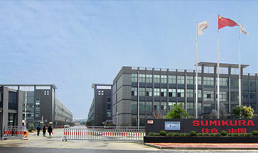
住所
中国浙江省徳清県逸仙路265号
海外の市場:+86 572-883-2016



